A
ZX81's keyboard is frustrating to use. Especially for games. One too many times, you find your finger isn't quite over the pad when you have to make that crucial jump...
It's easy to use an emulator, but personally I don't get the same buzz.
My first computer, probably in '82 was a secondhand ZX81 which had been screwed to a board along with some kind of aftermarket keyboard (which really wasn't very good).
So for that reason I feel perfectly OK about sorting myself out with something similar now.
After looking at many options (including the ZX-Key, which looks excellent and the Minstrel keyboard which has tactile switches) I noticed while recapping a Spectrum +2 that the keyboard connections are very similar to the 81's:
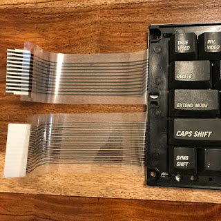 There are more lines because the later spectrums have many more keys. But some study of the matrix diagrams made me think that they were compatible* if you take the first five and the first eight lines from those ribbons.
I *really* like these keyboards. They're very usable. You can type on them easily, which I don't find with the 'plus' keyboards. This one is from a very dead black +2A which I have decided is now a donor.
This first experiment was a prototype or proof of concept. I used Dipsy here, who has an issue 3 board.
 The first step was to 'break out' the ZX81 keyboard connections. I took the connectors off the PCB and used a ribbon cable to extend them outside the 81's case. The ribbon doubles back neatly under the PCB, out of the expansion slot at the back while still allowing the ram pack to fit.
 I take a 'minimum damage' approach, so rather than trim the ends of the ribbons, I made slots in the connectors. These are easy to replace, and the +2A membrane isn't! Note that the connections don't exactly match the 81's*. I found that two half-rows were switched and had to reverse connections 3 & 4 on the 8-way connector**. I find this a little bizarre because otherwise the spectrum keyboards appear to be an extension of the 81's.
 That worked well. I found that even the space bar and shift keys work as expected. The only odd thing is that the small symbol shift keys on the Spectrum keyboard make a '.' character and the '.' key doesn't work. I may look into that sometime but it's not a big deal.
The problem with this is that so many bits are flapping around on the desk. But this wasn't meant to be the finished solution.
For phase 2, I decided that I wanted the zeddy's own keyboard to remain usable, and for the cable to be unpluggable at both ends. And for the whole thing to be easily reversible.
The hardest part of this whole project was finding the right connectors. I wanted them to be easy to plug and unplug but to be robust when in place. I found that these headers come in male and female and are spaced correctly. This is Tinky Winky, who has an issue 1 board and more importantly already has a ZX-CCB fitted for a really great composite output.
 I don't suppose it matters whether you attach the male or female connector to the board. I settled on doing it this way and having the females on both ends of the ribbon. These were very secure when in place. There's no picture but I soldered the ribbon to the female connectors so that it was already 'doubled back' and sits very neatly under the PCB and goes out of the expansion port. I used a 14-way ribbon and didn't bother to remove the spare line in case it was useful later.
 This is t'other end (the underside of the real keyboard). The PCB edge connector solved a lot of problems. I glued it into place and I presume will prise off if necessary. This one doesn't have the locator so both ribbons slot in. I glued a piece of card to the non-contact side of each ribbon so that they pushed firmly into the edge connector (a cut-up business card was perfect). The edge connector's two rows meant that the ribbons (one up, one down) would fit neatly.
The reason for the additional header pins is because the pins on the edge connector aren't quite long enough to make a firm fit into the plugs. This also means that I can see easily where the plugs go (and the addition of a spot of tipp-ex will make sure they always go the right way round.)
 Here's the finished result looking very neat indeed and working very well. Some rubber feet finished the job off (high enough to give clearance for the connectors underneath). Those are pretty grippy and I am amazed at how solid and positive the keyboard feels now.

 The next step is to look at some of those spare keys and see whether I might be able to hook them up. Particularly the cursor keys - for some games it'll be nice to have those doubling-up the 5,6,7,8 or possibly Q,A, O and P.
I had been planning to make stickers for the keytops (possibly by cutting up a membrane keyboard overlay). But I've abandoned that idea. This looks so neat as it is and It's easy to look at the zeddy's own keyboard for reference.
** edit. When I first wrote this post I said 2&3 on the 5-way connector which is wrong.
It's easy to use an emulator, but personally I don't get the same buzz.
My first computer, probably in '82 was a secondhand ZX81 which had been screwed to a board along with some kind of aftermarket keyboard (which really wasn't very good).
So for that reason I feel perfectly OK about sorting myself out with something similar now.
After looking at many options (including the ZX-Key, which looks excellent and the Minstrel keyboard which has tactile switches) I noticed while recapping a Spectrum +2 that the keyboard connections are very similar to the 81's:

I *really* like these keyboards. They're very usable. You can type on them easily, which I don't find with the 'plus' keyboards. This one is from a very dead black +2A which I have decided is now a donor.
This first experiment was a prototype or proof of concept. I used Dipsy here, who has an issue 3 board.


The problem with this is that so many bits are flapping around on the desk. But this wasn't meant to be the finished solution.
For phase 2, I decided that I wanted the zeddy's own keyboard to remain usable, and for the cable to be unpluggable at both ends. And for the whole thing to be easily reversible.
The hardest part of this whole project was finding the right connectors. I wanted them to be easy to plug and unplug but to be robust when in place. I found that these headers come in male and female and are spaced correctly. This is Tinky Winky, who has an issue 1 board and more importantly already has a ZX-CCB fitted for a really great composite output.


The reason for the additional header pins is because the pins on the edge connector aren't quite long enough to make a firm fit into the plugs. This also means that I can see easily where the plugs go (and the addition of a spot of tipp-ex will make sure they always go the right way round.)


I had been planning to make stickers for the keytops (possibly by cutting up a membrane keyboard overlay). But I've abandoned that idea. This looks so neat as it is and It's easy to look at the zeddy's own keyboard for reference.
** edit. When I first wrote this post I said 2&3 on the 5-way connector which is wrong.
Comments
Post a Comment