I
've had a project going to make a perfectly-working and perfect-looking Spectrum +2 from two non-working ones.
One (a car boot find from many years ago) has never worked, the other I bought and used quite a bit in the 90s. When switching it on again recently it ran fine for a little while and then vertical stripes appeared.
I'll write separately about getting a working board from these two and putting it in the best case of the two.
Because of that new vertical stripe problem, I checked out both PSUs, which have +5v, +12V and -12V. (Though the -12V is only used for the serial out I think). Both measured fine except for the -12V.
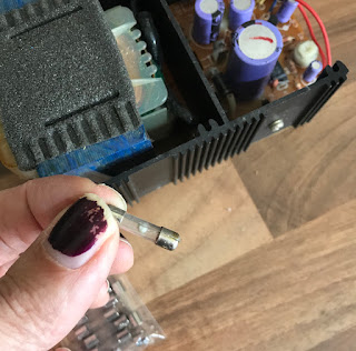
On delving deeper I found some disturbing things. In both cases it appeared that this fuse had blown. It turns out that although this one looked blown at first glance, someone has soldered wire across it. I don't know whether this is fusewire of the appropriate rating.

That's connected to a low-resistance, high wattage resistor. In both cases this resistor was open-circuit and in one case it had blown spectacularly.
After replacing that resistor (with more stonky replacements) one supply appeared to work, although its -12V was measuring -20V

The other didn't. On switching it on briefly there was smoke from that same resistor. C3 connects the output of that resistor to ground and was measuring as short-circuit. That may have broken earlier when the fuse/resistor blew, but it seems more likely that its short circuit was the cause of those other components blowing (20V straight to ground).
This has convinced me that it's worth replacing electrolytic capacitors in anything that you have open. It doesn't cost much for good-quality replacements and it's easy to do.
Replacing that single capacitor gave me one supply which was measuring fine on all voltages. But I'm a bit hesitant about using that one. It's missing that little strip of PCB at the top which carries the second fuse. Were some of these PSUs built without that part? Or has someone removed it deeming it not necessary? If you know, please tell me.
(I have been using this circuit diagram which doesn't show the second fuse. Maybe it wasn't there in all models.)
With all this in mind and given that I'd like a reliable supply for this computer, I set about doing further work on the one that does have that extra little board. The -12V measuring -20V probably meant that the -12V regulator isn't working, and the fact that it's the next component in the chain after the blown fuse and resistor, it seemed unsurprising that it had broken too.
It has a 7812 and 17912 for the +12 and -12. Note that the +12V 7812 (IC2) is the big one bolted to the heatsink. Its negative partner, the 7912 (IC3) is a much smaller component looking more like a regular transistor. I replaced both of these with nice big 1.5A components.
I replaced all electrolytic capacitors. Is this over the top? That supply now works fine and with so many parts replaced by new, better quality and higher-rated components, I feel that I can really depend on this supply.

After the obligatory bath and scrub for the case, it went back together and now looks and works a treat.


One (a car boot find from many years ago) has never worked, the other I bought and used quite a bit in the 90s. When switching it on again recently it ran fine for a little while and then vertical stripes appeared.
I'll write separately about getting a working board from these two and putting it in the best case of the two.
Because of that new vertical stripe problem, I checked out both PSUs, which have +5v, +12V and -12V. (Though the -12V is only used for the serial out I think). Both measured fine except for the -12V.
On delving deeper I found some disturbing things. In both cases it appeared that this fuse had blown. It turns out that although this one looked blown at first glance, someone has soldered wire across it. I don't know whether this is fusewire of the appropriate rating.


That's connected to a low-resistance, high wattage resistor. In both cases this resistor was open-circuit and in one case it had blown spectacularly.
After replacing that resistor (with more stonky replacements) one supply appeared to work, although its -12V was measuring -20V

The other didn't. On switching it on briefly there was smoke from that same resistor. C3 connects the output of that resistor to ground and was measuring as short-circuit. That may have broken earlier when the fuse/resistor blew, but it seems more likely that its short circuit was the cause of those other components blowing (20V straight to ground).
This has convinced me that it's worth replacing electrolytic capacitors in anything that you have open. It doesn't cost much for good-quality replacements and it's easy to do.
Replacing that single capacitor gave me one supply which was measuring fine on all voltages. But I'm a bit hesitant about using that one. It's missing that little strip of PCB at the top which carries the second fuse. Were some of these PSUs built without that part? Or has someone removed it deeming it not necessary? If you know, please tell me.
(I have been using this circuit diagram which doesn't show the second fuse. Maybe it wasn't there in all models.)
With all this in mind and given that I'd like a reliable supply for this computer, I set about doing further work on the one that does have that extra little board. The -12V measuring -20V probably meant that the -12V regulator isn't working, and the fact that it's the next component in the chain after the blown fuse and resistor, it seemed unsurprising that it had broken too.
It has a 7812 and 17912 for the +12 and -12. Note that the +12V 7812 (IC2) is the big one bolted to the heatsink. Its negative partner, the 7912 (IC3) is a much smaller component looking more like a regular transistor. I replaced both of these with nice big 1.5A components.
I replaced all electrolytic capacitors. Is this over the top? That supply now works fine and with so many parts replaced by new, better quality and higher-rated components, I feel that I can really depend on this supply.

After the obligatory bath and scrub for the case, it went back together and now looks and works a treat.


Good to know, thanks Baze.
ReplyDelete